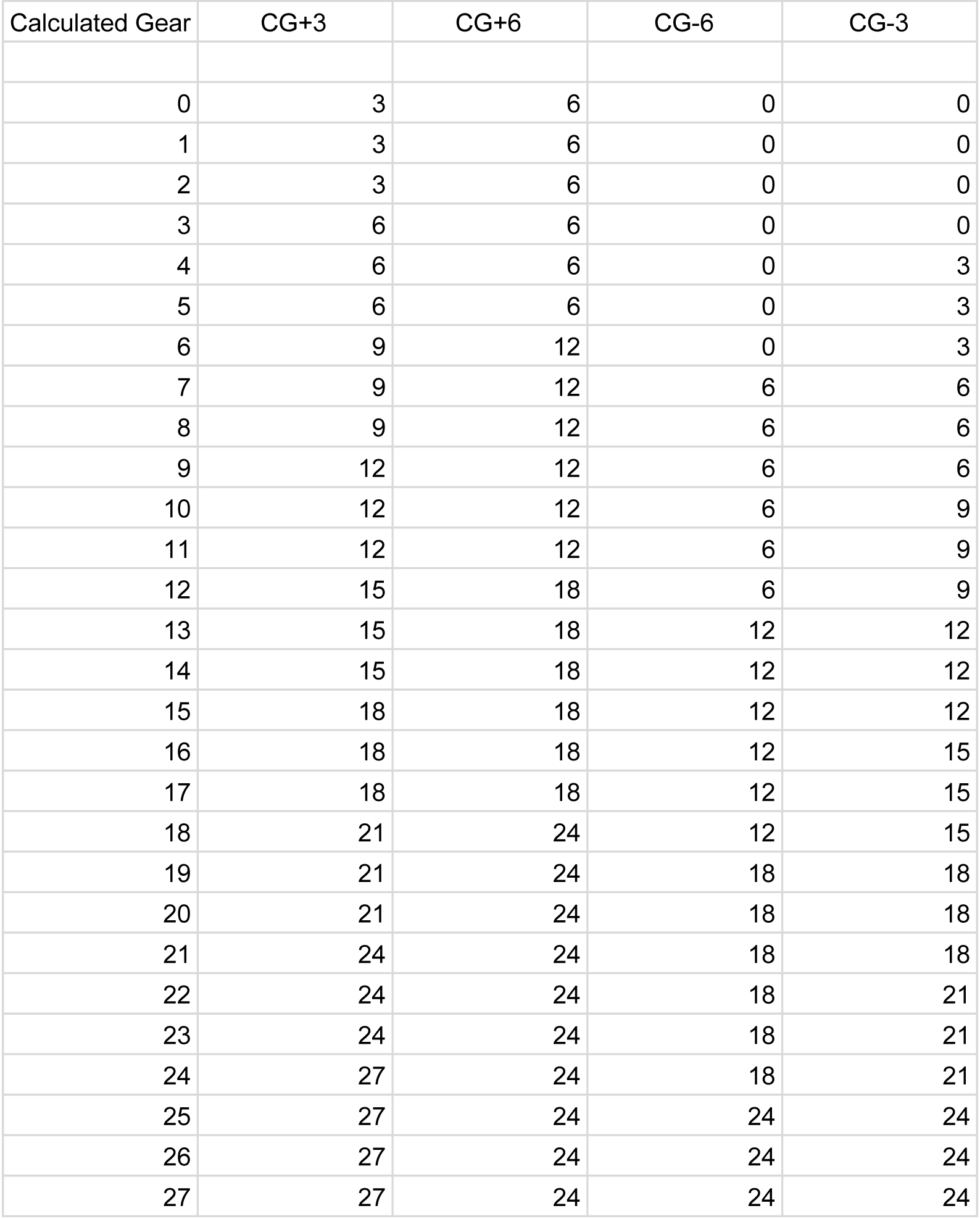
Here is my logic as a spreadsheet


Here’s the patch. So much easier and clearer, I think I’ll delete the previous calculation versions of this. Do you agree with the calculations? slightly different from yours, I think.
LTP for F-RQ all LUTs.xodball (9.1 KB)
Will check it when I get home from work
Don’t delete anything, it’s part of the record of this whole journey!
Ok. Here is RTP. I think to combine the two, LTP and RTP onto one patch, you need to make each one into its own encapsulated patch. Never did that. But it’s really powerful and I’ll learn. It’s important because it lets you put together very large projects cleanly.
RTP for F-RQ all LUTs.xodball (9.1 KB)
I just picked up my steering wheel, how many wires do I need to be running from the RTP and LTP?
Need to be able to get them all through this bottle neck
To do it the straightforward way, you would need 10 - One common going to the power switch the LTP and the RTP. Add 9 different switch pushes to read - power push plus 4 from the LTP and 4 from the RTP = 10 wires, 9 inputs for the controller to read.
You can drastically reduce that to 6 by taking advantage of the fact that only one button or switch gets pressed at a time. You bring in a +5v and a Ground (that’s 2). When any key is pressed you get a 4 bit code, an encoding of the one that is pressed. (that’s 4 more). Thus only 6 wires are needed. Easiest code is binary 8-4-2-1, but others are shown in the link below.
You can use two 74HC148 chips to make a 16 bit (to 4 bit) encoder. That would cover 15 push switches since you don’t want to use the 0 code as a button press.
Alternative - you can use a totally passive diode matrix to do the same and make an 11
bit to 4 bit, which would cover 10 switches.
This link gives an example of both.
https://learnabout-electronics.org/Digital/dig44.php
There is an analog “resistor ladder hack” that could read 10 switches with a single analog read, but it would work only if you had two wires from each of the 10 switches. The touch pads, however, I believe, have a common pin and 4 outputs.
Ok I admit you lost me at the encoding bit.
What bit of XOD-ery majick can we use, so all I have to do is figure out the wiring past the roadblock, and then connect the wiring to the linear servo motors, (when I actually get them)
What happens is this. Since you are not playing chords, pressing multiple switches at a time, the steering wheel electronics needs only to tell you which button, if any, is being pressed. The circuit does that by, on the receiving side, after connecting the 4 resistors (I would use 2.5k) to the X0-X3 wires and Ground to the resistors, your XOD code does 4 digital reads on the wires X0-X3. You use four conditionals to convert the X0 to value 1 if High else 0, the X1 to a 2 if High else 0, the X2 to a 4 if High else 0, and the X3 conditional to another 2 if HIgh or a 0.
I would connect the 9 input switches to rows 1 through 9 of the diode matrix.
Then a 4 input adder adds those 4 outputs of the 4 conditionals and you get a number 0 or 1-through 9. 0 means nothing pressed. 1 through 9 mean your Power up, the LTP, or the RTP has been pressed, however you assign the switch and touch pad pins to those rows.
It’s as if the steering yells out a number 0-9 whenever asked. Instead of one number it yells out 4 numbers for the 4 binary digit values, 2-4-2-1. I would use the 8-4-2-1 so you can add up to 5 more switches like a horn or the ejection seat. It would yell, or let you read “Low High High Low” instead of yelling six, for example. XOD would always add it up and you’d only hear, “A six”.
The red box encloses what goes in your steering box. Note that only 5 wires come out.
Diodes are needed so that if any of the X wires goes High, it doesn’t cause any of the other wires to go high. No current flows backward through a diode. If an X wire gets no current, there is no voltage drop across its resistor, resulting in its voltage not getting raised above Ground. If an X wire is High and only one switch is closed, there is a unique combination of the 4 X wire High/Low voltages that adds up to which switch was closed.
You can and should use thin, high gauge wire; Only very low current (2ma) goes through them. Use stranded if the wires will get constantly bent a lot, perhaps a slightly larger gauge.
I think the electronics side should use large loops of wire so the flexing is small on any small section.
( https://www.amazon.com/slp/flexible-stranded-wire/6d54q7enwznh7gf )
Should be able to make the diode matrix easy enough.
How do I make it to 8,4,2,1? Just in case 
Do I then need a decoder patch from XOD to read the pulses and then send the signals to the front and rear linear servo motors
So 4 wires feeding back out through the steering wheel road block, coming from the diode matrix, inside the steering wheel?
And the encoder is inside the XOD bit of the circuitry?
How does the encoding bit connect to the linear servo motors, through the Gear Look Up Tables? Which are interconnected with the Gear Position Index.
Starting in OG1/CG0
So once I press eg RTP + (next calculated gear OG1/CG0 -> OG2/CG1 the GLUT automatically tells the linear servo motors to move the rear derailleur one gear cog outwards, and the Gear Position Index now shows 2.
Is that correct?
How do I make it to 8,4,2,1? Just in case
Starting at switch 5 and going up through switch 9, you change the combination or diodes to Xlines. Ex. 5 becomes 0,4,0,1 (2 diodes, one to X2 and 1 to X0). Thus 5 gets added up (as regular binary) a 4 and a 1 -->5. 9 becomes 8 and a 1.
Do I then need a decoder patch from XOD to read the pulses and then send the signals to the front and rear linear servo motors
Yes. It would start by adding the four X3 to X0 numbers, each produced via a simple conditional node. You would use a 4 input adder node. Each of the X lines would come from a digital read (true or false), and that would go to a conditional node. For example, the conditional having X2 as its input would have 4 and 0 as its true and false values.
So 4 wires feeding back out through the steering wheel road block, coming from the diode matrix, inside the steering wheel?
5 wires. The +5v needs to be fed in, too.
And the encoder is inside the XOD bit of the circuitry?
I think you mean he decoder, which is in XOD.
The encode is the diode matrix in the steering wheel.
How does the encoding bit connect to the linear servo motors, through the Gear Look Up Tables? Which are interconnected with the Gear Position Index.
You mean does the decoded number connect…
Yes
Starting in OG1/CG0
So once I press eg RTP + (next calculated gear OG1/CG0 -> OG2/CG1 the GLUT automatically tells the linear servo motors to move the rear derailleur one gear cog outwards, and the Gear Position Index now shows 2.
Is that correct?
Yes.
Yes. You can now proudly wear that geeky t-shirt, “There are 10 types of people in the world, those who know binary and those who don’t” 
Ok just took apart one of my spare XBox 360 steering wheels, (yes I do own 3 of them!) to have a look inside.
There are 20 wires coming out of the steering wheel, into the 1st loom, and 5 wires in the second loom, plus the earth/ground wire.
There are 13 switches on the Xbox 360 steering wheel. LTP UDLR, RTP UDLR, Xbox button, back button, and start button, plus two brake lever switches
So…
If I can transfer the 2 looms through the road block, by drilling out the shaft just big enough to get all the wires through, then apply 5v to the red wire in the 5 wires loom, I should be able to work out which wires run from each switch? Yes?
Yes. Perhaps the easiest way is using a multimeter, especially if it has audio continuity tester mode, signified by a diode symbol in the ohms (resistance mode). With two alligator clips, put the red on the red (would be 5v wire), and the black on one of the 13 switch wires. Then your hands are free to quickly press each button until you hear it beep or read < 0.5 ohm (if there’s no beep mode). Mark that wire with tape and write the switch name on it.) Or put it in your doc.
I take it you’re then going to use the diode matrix encoder in 8-4-2-1 mode and feed through the five external wires via thin, flexible (30 awg) wire. Right?
If you can power it up, and you are right about the encoder, one wire should always be high (5v); the other wires, when a switch is pressed, should each produce a unique combination of the 4 wires being high, like yours will (or would have).