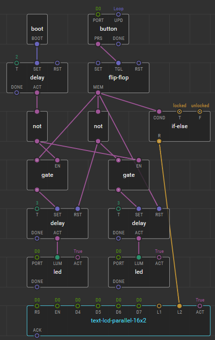
If debounce doesn’t work for you, you can start a delay timer when the button is pressed. Negate the delay-ACT output (using “not” node). You can now use this signal to either activate a “gate” node, or just “and” it with the button press output. Either solution will cause button press to be ignored while the delay is active.
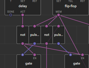
Usually “gate” would be used to disable a button like this:

But in this case, a simple “and” has the same affect:

In both cases, the “defer” node is used only because you are feeding output back up the program, creating a loop. XOD will not allow loops like this without the “defer” because it would create unstable output depending on order of execution.
You want the button to be active when the delay node is not active, hence the “not” node to invert the output that is fed back up to the “gate” or “and” node.
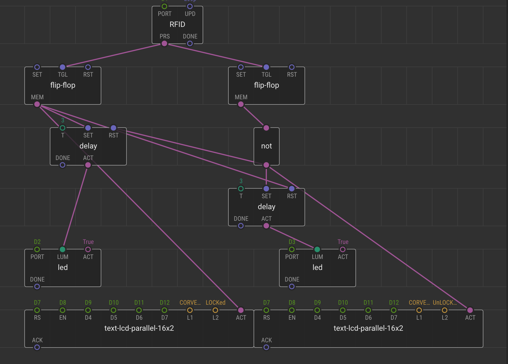
Note that the delay and flip-flop are triggered by a pulse. In this case, we are feeding boolean output to them. There will be an implicit “pulse-on-true” used to convert boolean to pulse. This means they are only triggered on change from false to true. If your FOB reader is glitchy, and tends to turn off and back on while the card is present (or if you remove the FOB and return it shortly after), that is when another pulse is sent to flip-flop & delay. If you want the delay to keep resetting as long as the FOB reader is pulsing, you can connect the delay-SET directly to the reader instead of feeding it from the “gate” or “and” node. As long as the reader glitches before the delay timer expires, it would reset the delay timer. You would have to remove the FOB for the timeout period, then place it in the reader again to change lock state a 2nd time with this modification. As written above, the 1st glitch after the delay timer expires would change lock state again (which will happen even with the modification if the glitch doesn’t happen within the timeout period to set the delay timer again).
FYI: You will have less risk and probably save memory if you only use one lcd node and change the input pins instead of having multiple lcd nodes.
Since there are only two choices, you can change the text using an if-else. The flip-flop output will be the if-else-COND

If you wanted more choices, you could use “switch-case”, but in this case, “select” would probably work better. The same input that you now tie to your lcd-ACT pins would instead link to the select-S# pins.

By having only one lcd node, you also make it easier to modify the program in the future since there is only one place to change lcd configuration and all possible lcd values feed to the same location. Your implementation is not “wrong”, but it probably uses more memory and is higher risk (bad things happen if both become active at the same time–a low risk in this case…).
If the 1st line of text also changes, you can change it using the same technique.
There are exceptions, but as a general rule, if you have a single piece of hardware like LCD, there should probably be one node controlling it. If the LCD ends up hidden inside a patch used multiple times, you will end up with multiple LCD nodes and controlling the ACT pin becomes crucial. With only one LCD node, you can just leave ACT True; the node doesn’t “fire” unless one of the pins changes and ACT is True.